Clean vectors from noisy point clouds
Edges and corners are usually where a point cloud is fuzziest. If you only snap into the cloud, you trace that noise. Pointcloud Manager separates drawing from the cloud: you clean the cloud, draw on a plane and correct every vertex deliberately.
The problem: the line inherits the scatter
A line that simply follows the cloud points inherits their scatter. At curbs, building edges and wall corners the points fray; the polyline ends up rounded or wavy and misses the true alignment of the edge. In CAD this only shows later, when lengths and right angles do not add up.
This workflow avoids that: remove the stray points first, draw in a controlled way, then adjust each vertex and snap only where it makes sense.
How it works
Clean the cloud
Outlier removal deletes isolated points. There is a statistical method (SOR) and a radius method; a red preview shows beforehand which points would be affected, with a counter. Only “Apply” removes them.
For individual disturbances – a vehicle at the edge, vegetation in front of a wall – mark them with the lasso (Alt + drag; freehand, rectangle or circle). Again a red preview with a counter shows what would go. “Delete + fill” replaces the spot with points that follow the ground.
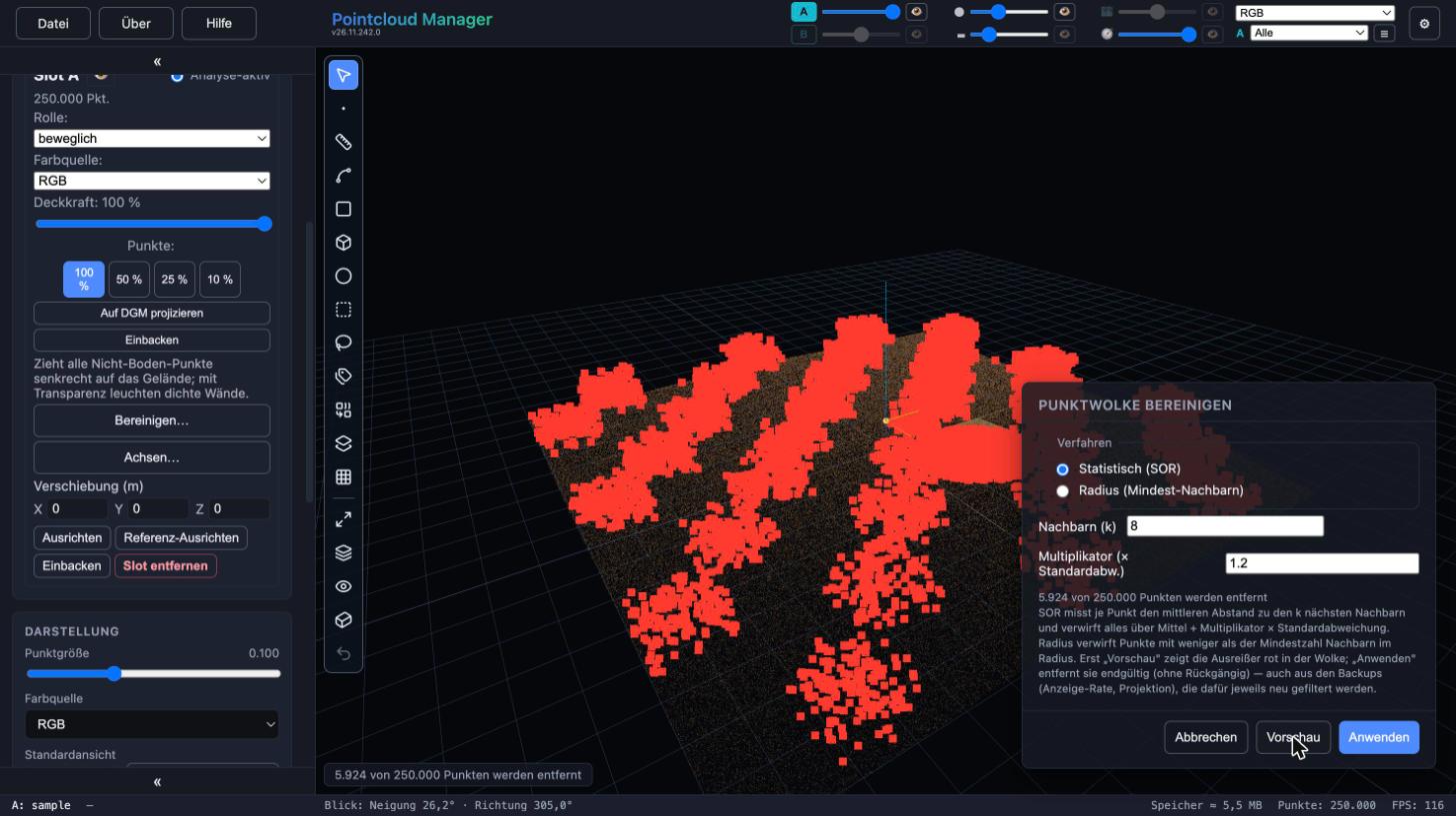
Point cloud cleanup dialog with a red outlier preview and counter in the sample cloud. Sample data, German interface. Draw on a drawing plane
Instead of hunting for each point in the cloud, set an area as the drawing plane (“Set drawing plane here” in the “Alignment” panel). The plane takes over origin, direction and grid spacing; the grid follows the pointer. New points are placed on the plane, and optionally snap to grid points (Settings).
For edges that do not lie in one plane, pick an existing edge as reference: the alignment grid shows parallels (red) and perpendiculars (green) to it. “Drape” lays finished vertices vertically onto the terrain model or the drawing plane; only Z changes, X and Y stay exact.
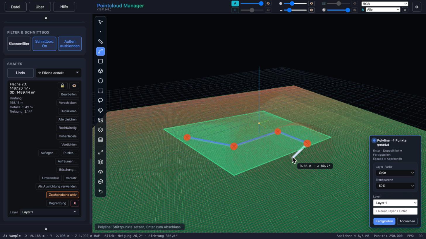
Polyline with live dimension being drawn on an area set as the drawing plane. Sample data, German interface. Move vertices deliberately
A selected vertex shows the gizmo with the X, Y, Z axes and the XY, ZY, ZX planes; the third axis stays constant. The X, Y or Z keys lock movement to one axis. Holding G moves horizontally while the height stays. Alt restricts movement to exactly horizontal or vertical 90° directions.
The H key shows the height of the selected point. Shift + click on a second point selects everything in between and moves it together. Because cloud points hide parts of the line, you can see how the drawing sits in the cloud and align it along the visible edge.
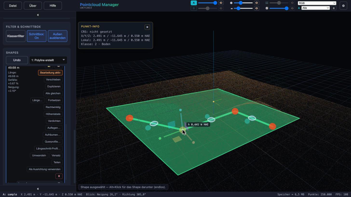
Selected vertex of a polyline with axis and plane gizmo and height label. Sample data, German interface. Snap and square up on purpose
Snapping is a decision here, not automatic. While drawing, Shift near an edge snaps to the edge midpoint of existing shapes, including areas. While moving a vertex, Shift snaps to the visible point cloud or other vertices; Shift + Ctrl (Cmd) snaps to vertices only and leaves the cloud out – useful where several shapes meet in a corner.
While drawing you can type a length: the current segment gets exactly that length, like CAD-style length entry. Combined with the 90° lock (Alt or R) this gives exact, right-angled segments.
“Right-angle” on the shape card squares edges to a chosen reference edge, but only within a tolerance (default 10°). Oblique angles stay oblique, evenly curved chains are left alone. “Clean up…” removes duplicate and redundant intermediate points before delivery without moving any coordinates.
Export as DXF
Under File → Export → “Export DXF” you choose the layers that go into the file and can limit it to the boundary area. There are options for labels, arcs, DXF format and height system; elevation labels can go along as MTEXT. The header of the layer list states “n of m layers, k shapes” before you export.
Result
A drawing whose vertices you placed deliberately, organized on layers and delivered as DXF for CAD. Cloud and drawing stay visible together in the viewer, so you can check the position against the as-built situation before you export.
Limits
- Cleanup and lasso act on the loaded cloud, not on the original file, and cannot be undone. Reopening the file brings back the complete cloud; to keep the cleaned state, export the cloud as LAS or LAZ.
- The lasso only captures visible points in the active slot (class filter and section box apply). With display reduction below 100 %, deleting is refused.
- “Set drawing plane here” only works for areas. “Right-angle” only squares what lies within the tolerance; if nothing is in range, nothing changes.
- Lines are drawn by hand. There is no automatic edge detection.
More in the manual
The complete description of the functions used is in the manual:
Status: app version 26.11.242.0
More features
Work with your own point cloud.
Open point clouds, trace existing features and export geometry for CAD — directly in your browser, with point cloud data processed locally.
Try free for 14 daysRequest a demo